  1
  2
  3
  4
  5
  6
  7
  8
  9
 10
 11
 12
 13
 14
 15
 16
 17
 18
 19
 20
 21
 22
 23
 24
 25
 26
 27
 28
 29
 30
 31
 32
 33
 34
 35
 36
 37
 38
 39
 40
 41
 42
 43
 44
 45
 46
 47
 48
 49
 50
 51
 52
 53
 54
 55
 56
 57
 58
 59
 60
 61
 62
 63
 64
 65
 66
 67
 68
 69
 70
 71
 72
 73
 74
 75
 76
 77
 78
 79
 80
 81
 82
 83
 84
 85
 86
 87
 88
 89
 90
 91
 92
 93
 94
 95
 96
 97
 98
 99
100
101
102
103
104
105
106
107
108
109
110
111
112
113
114
115
116
117
118
119
120
121
122
123
124
125
126
127
128
129
130
131
132
133
134
135
136
137
138
139
140
141
142
143
144
145
146
147
148
149
150
151
152
153
154
155
156
157
158
159
160
161
162
163
164
165
166
167
168
169
170
171
172
173
174
175
176
177
178
179
180
181
182
183
184
185
186
187
188
189
190
191
192
193
194
195
196
197
198
199
200
201
202
203
204
205
206
207
208
209
210
211
212
213
214
215
216
217
218
219
220
221
222
223
224
225
226
227
228
229
230
231
232
233
234
235
236
237
238
239
240
241
242
243
244
245
246
247
248
249
250
251
252
253
254
255
256
257
258
259
260
261
262
263
264
265
266
267
268
269
270
271
272
273
274
275
276
277
278
279
280
281
282
283
284
285
286
287
288
289
290
291
292
293
294
295
296
297
298
299
300
301
302
303
304
305
306
307
308
309
310
311
312
313
314
315
316
317
318
319
320
321
322
323
324
325
326
327
328
329
330
331
332
333
334
335
336
337
338
339
340
341
342
343
344
345
346
347
348
349
350
351
352
353
354
355
356
357
358
359
360
361
362
363
364
365
366
367
368
369
370
371
372
373
374
375
376
377
378
379
380
381
382
383
384
385
386
387
388
389
390
391
392
393
394
395
396
397
398
399
400
401
402
403
404
405
406
407
408
409
410
411
412
413
414
415
416
417
418
419
420
421
422
423
424
425
426
427
428
429
430
431
432
433
434
435
436
437
438
439
440
441
442
443
444
445
446
447
448
449
450
451
452
453
454
455
456
457
458
459
460
461
462
463
464
465
466
467
|
'The MIT License (MIT)
'Copyright (c) 2019 Chipnetics Computing (www.chipnetics.com)
'Permission is hereby granted, free of charge, to any person obtaining a copy of
'this software and associated documentation files (the "Software"), to deal in
'the Software without restriction, including without limitation the rights to
'use, copy, modify, merge, publish, distribute, sublicense, and/or sell copies of
'the Software, and to permit persons to whom the Software is furnished to do so,
'subject to the following conditions:
'The above copyright notice and this permission notice shall be included in all
'copies or substantial portions of the Software.
'THE SOFTWARE IS PROVIDED "AS IS", WITHOUT WARRANTY OF ANY KIND, EXPRESS OR
'IMPLIED, INCLUDING BUT NOT LIMITED TO THE WARRANTIES OF MERCHANTABILITY, FITNESS
'FOR A PARTICULAR PURPOSE AND NONINFRINGEMENT. IN NO EVENT SHALL THE AUTHORS OR
'COPYRIGHT HOLDERS BE LIABLE FOR ANY CLAIM, DAMAGES OR OTHER LIABILITY, WHETHER
'IN AN ACTION OF CONTRACT, TORT OR OTHERWISE, ARISING FROM, OUT OF OR IN
'CONNECTION WITH THE SOFTWARE OR THE USE OR OTHER DEALINGS IN THE SOFTWARE.
$regfile = "attiny2313.DAT"
$hwstack = 40
$swstack = 20
$framesize = 24
$crystal = 8000000
'DDRx - Port X Data Direction Register
'Writing 1 in the pin location makes output pin. 0 makes input pin
'Data Direction Register. 0 = Input, 1 = Output
Ddrb = &B11111111 ' Output for a,b,x,y,up,down,left,right
Ddrd = &B00001111 ' [5]Input for Serial | [3,2,1,0] Output for select,start,l,r
Ddra = &B00000011 ' [1]Output for clk | [0]Output for latch
'PINx - Port X Input Pins Register (READING)
'To READ the values on the pins of PortX you read the values that are on the pin
'register.
'PORTx - Port X Data Register. (OUTPUTTING)
'Stores logic values currently being OUTPUTTED on the physical pinds of PORTx
Portb = &B11111111
Portd = &B00101111 'Internal pullup on D.5 - set to input but outputting 1
Porta = &B00000010
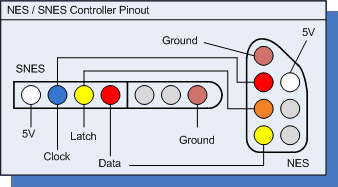
Controller_latch Alias Porta.0 'Output
Controller_clk Alias Porta.1 'Output
Controller_serial Alias Pind.5 'Input
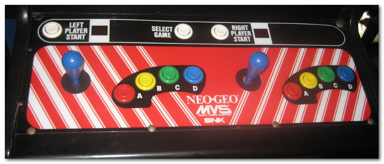
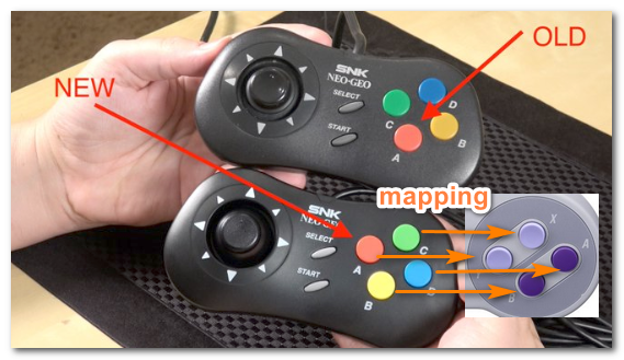
Pad_y Alias Portb.0 'Neo Geo A
Pad_b Alias Portb.1 'Neo Geo B
Pad_x Alias Portb.2 'Neo Geo C
Pad_a Alias Portb.3 'Neo Geo D
Pad_up Alias Portb.4
Pad_down Alias Portb.5
Pad_left Alias Portb.6
Pad_right Alias Portb.7
Pad_select Alias Portd.0
Pad_start Alias Portd.1
Pad_l Alias Portd.2
Pad_r Alias Portd.3
'--------------------------------------------------------------------------------
' Every 16.67ms (60hz), SNES sends out 12us wide +ve data latch pulse pin 3
' 6us after fall of latch:
' 16 data clock pulses output on pin 2, 50% duty cycle at 12uS per cycle (6 low, 6 high)
' Controller serially shift latch button states on pin 4 every rising edge of clk
' CPU samples on every falling edge.
' Logic high on samples mean the button is NOT depressed.
' At end of 16 cycle sequence, serial data line driven low until next data latch pulse
' Clk cycle:
' 1 B | 2 Y | 3 Select | 4 Start | 5 Up | 6 Down | 7 Left | 8 Right | 9 A
' 10 X | 11 L | 12 R | 13->16 None (always High)
'
' Serial data train takes (6uS high + 6uS low) X 16 = 192uS
' SNES is sampling at 16.67mS -> 16667uS which means it is wayyy undersampling data.
'
' Here we sample fast as possible, much more above what the SNES CPU would which will
' Achieve a much more parallel-like output to the NEO GEO.
'
' Neo Geo CPU probably does not poll this fast (60hz?) so when it does sample everything
' will be setup high/low and will appear as parallel data.
'--------------------------------------------------------------------------------
Pollcontroller:
'Controller clock normally high
Controller_clk = 1
'12uS wide data latch pulse
'At 8MHz each loop is 0.375uS
Controller_latch = 1
ldi R17, $21 '
Data_latch_pulse_width:
dec R17
brne data_latch_pulse_width
Controller_latch = 0
'''''''''' B BUTTON START '''''''''''''''''''''''
Controller_clk = 1 'Controller latches data rising edge
ldi R17, $10 '
B_clock_pulse_width:
dec R17
brne b_clock_pulse_width
Controller_clk = 0 'CPU fetches falling edge
' First sample is on the falling edge. (for B Button)
If Controller_serial = 0 Then
Pad_b = 0
Else
Pad_b = 1
End If
ldi R17, $F '
B_low_pulse_width:
dec R17
brne b_low_pulse_width
NOP
'''''''''' B BUTTON END '''''''''''''''''''''''
'''''''''' Y BUTTON START '''''''''''''''''''''''
Controller_clk = 1 'Controller latches data rising edge
ldi R17, $10 '
Y_clock_pulse_width:
dec R17
brne y_clock_pulse_width
Controller_clk = 0 'CPU fetches falling edge
' First sample is on the falling edge. (for Y Button)
If Controller_serial = 0 Then
Pad_y = 0
Else
Pad_y = 1
End If
'12 uS Remainder of Low Pulse (6uS = 16x0.375us)
ldi R17, $F '
Y_low_pulse_width:
dec R17
brne y_low_pulse_width
NOP
'''''''''' Y BUTTON END '''''''''''''''''''''''
'''''''''' SELECT BUTTON START '''''''''''''''''''''''
Controller_clk = 1 'Controller latches data rising edge
ldi R17, $10 '
Select_clock_pulse_width:
dec R17
brne select_clock_pulse_width
Controller_clk = 0 'CPU fetches falling edge
' First sample is on the falling edge. (for Select Button)
If Controller_serial = 0 Then
Pad_select = 0
Else
Pad_select = 1
End If
'12 uS Remainder of Low Pulse
ldi R17, $F '
Select_low_pulse_width:
dec R17
brne select_low_pulse_width
NOP
'''''''''' SELECT BUTTON END '''''''''''''''''''''''
'''''''''' START BUTTON START '''''''''''''''''''''''
Controller_clk = 1 'Controller latches data rising edge
ldi R17, $10 '
Start_clock_pulse_width:
dec R17
brne start_clock_pulse_width
Controller_clk = 0 'CPU fetches falling edge
' First sample is on the falling edge. (for Start Button)
If Controller_serial = 0 Then
Pad_start = 0
Else
Pad_start = 1
End If
'12 uS Remainder of Low Pulse
ldi R17, $F '
Start_low_pulse_width:
dec R17
brne start_low_pulse_width
NOP
'''''''''' START BUTTON END '''''''''''''''''''''''
'''''''''' up BUTTON START '''''''''''''''''''''''
Controller_clk = 1 'Controller latches data rising edge
ldi R17, $10 '
Up_clock_pulse_width:
dec R17
brne up_clock_pulse_width
Controller_clk = 0 'CPU fetches falling edge
' First sample is on the falling edge. (for Up Button)
If Controller_serial = 0 Then
Pad_up = 0
Else
Pad_up = 1
End If
'12 uS Remainder of Low Pulse
ldi R17, $F '
Up_low_pulse_width:
dec R17
brne up_low_pulse_width
NOP
'''''''''' up BUTTON END '''''''''''''''''''''''
'''''''''' down BUTTON START '''''''''''''''''''''''
Controller_clk = 1 'Controller latches data rising edge
ldi R17, $10 '
Down_clock_pulse_width:
dec R17
brne down_clock_pulse_width
Controller_clk = 0 'CPU fetches falling edge
' First sample is on the falling edge. (for Down Button)
If Controller_serial = 0 Then
Pad_down = 0
Else
Pad_down = 1
End If
'12 uS Remainder of Low Pulse
ldi R17, $F '
Down_low_pulse_width:
dec R17
brne down_low_pulse_width
NOP
'''''''''' down BUTTON END '''''''''''''''''''''''
'''''''''' left BUTTON START '''''''''''''''''''''''
Controller_clk = 1 'Controller latches data rising edge
ldi R17, $10 '
Left_clock_pulse_width:
dec R17
brne left_clock_pulse_width
Controller_clk = 0 'CPU fetches falling edge
' First sample is on the falling edge. (for Left Button)
If Controller_serial = 0 Then
Pad_left = 0
Else
Pad_left = 1
End If
'12 uS Remainder of Low Pulse
ldi R17, $F '
Left_low_pulse_width:
dec R17
brne left_low_pulse_width
NOP
'''''''''' left BUTTON END '''''''''''''''''''''''
'''''''''' right BUTTON START '''''''''''''''''''''''
Controller_clk = 1 'Controller latches data rising edge
ldi R17, $10 '
Right_clock_pulse_width:
dec R17
brne right_clock_pulse_width
Controller_clk = 0 'CPU fetches falling edge
' First sample is on the falling edge. (for Right Button)
If Controller_serial = 0 Then
Pad_right = 0
Else
Pad_right = 1
End If
'12 uS Remainder of Low Pulse
ldi R17, $F '
Right_low_pulse_width:
dec R17
brne right_low_pulse_width
NOP
'''''''''' right BUTTON END '''''''''''''''''''''''
'''''''''' a BUTTON START '''''''''''''''''''''''
Controller_clk = 1 'Controller latches data rising edge
ldi R17, $10 '
A_clock_pulse_width:
dec R17
brne a_clock_pulse_width
Controller_clk = 0 'CPU fetches falling edge
' First sample is on the falling edge. (for A Button)
If Controller_serial = 0 Then
Pad_a = 0
Else
Pad_a = 1
End If
'12 uS Remainder of Low Pulse
ldi R17, $F '
A_low_pulse_width:
dec R17
brne a_low_pulse_width
NOP
'''''''''' a BUTTON END '''''''''''''''''''''''
'''''''''' x BUTTON START '''''''''''''''''''''''
Controller_clk = 1 'Controller latches data rising edge
ldi R17, $10 '
X_clock_pulse_width:
dec R17
brne x_clock_pulse_width
Controller_clk = 0 'CPU fetches falling edge
' First sample is on the falling edge. (for X Button)
If Controller_serial = 0 Then
Pad_x = 0
Else
Pad_x = 1
End If
'12 uS Remainder of Low Pulse
ldi R17, $F '
X_low_pulse_width:
dec R17
brne x_low_pulse_width
NOP
'''''''''' x BUTTON END '''''''''''''''''''''''
'''''''''' l BUTTON START '''''''''''''''''''''''
Controller_clk = 1 'Controller latches data rising edge
ldi R17, $10 '
L_clock_pulse_width:
dec R17
brne l_clock_pulse_width
Controller_clk = 0 'CPU fetches falling edge
' First sample is on the falling edge. (for l Button)
If Controller_serial = 0 Then
Pad_l = 0
Else
Pad_l = 1
End If
'12 uS Remainder of Low Pulse
ldi R17, $F '
L_low_pulse_width:
dec R17
brne l_low_pulse_width
NOP
'''''''''' l BUTTON END '''''''''''''''''''''''
'''''''''' r BUTTON START '''''''''''''''''''''''
Controller_clk = 1 'Controller latches data rising edge
ldi R17, $10 '
R_clock_pulse_width:
dec R17
brne r_clock_pulse_width
Controller_clk = 0 'CPU fetches falling edge
' First sample is on the falling edge. (for r Button)
If Controller_serial = 0 Then
Pad_r = 0
Else
Pad_r = 1
End If
'12 uS Remainder of Low Pulse
ldi R17, $F '
R_low_pulse_width:
dec R17
brne r_low_pulse_width
NOP
'''''''''' r BUTTON END '''''''''''''''''''''''
''''''''''''''''''''''''''
''' UNMAPPED BUTTONS '''''
''''''''''''''''''''''''''
'''''''''' unmap1 BUTTON START '''''''''''''''''''''''
Controller_clk = 1 'Controller latches data rising edge
ldi R17, $10 '
Unmap1_clock_pulse_width:
dec R17
brne unmap1_clock_pulse_width
Controller_clk = 0 'CPU fetches falling edge
' First sample is on the falling edge.
If Controller_serial = 0 Then
NOP
Else
NOP
End If
'12 uS Remainder of Low Pulse
ldi R17, $F '
Unmap1_low_pulse_width:
dec R17
brne unmap1_low_pulse_width
NOP
'''''''''' unmap1 BUTTON END '''''''''''''''''''''''
'''''''''' unmap2 BUTTON START '''''''''''''''''''''''
Controller_clk = 1 'Controller latches data rising edge
ldi R17, $10 '
Unmap2_clock_pulse_width:
dec R17
brne unmap2_clock_pulse_width
Controller_clk = 0 'CPU fetches falling edge
' First sample is on the falling edge.
If Controller_serial = 0 Then
NOP
Else
NOP
End If
'12 uS Remainder of Low Pulse
ldi R17, $F '
Unmap2_low_pulse_width:
dec R17
brne unmap2_low_pulse_width
NOP
'''''''''' unmap2 BUTTON END '''''''''''''''''''''''
'''''''''' unmap3 BUTTON START '''''''''''''''''''''''
Controller_clk = 1 'Controller latches data rising edge
ldi R17, $10 '
Unmap3_clock_pulse_width:
dec R17
brne unmap3_clock_pulse_width
Controller_clk = 0 'CPU fetches falling edge
' First sample is on the falling edge.
If Controller_serial = 0 Then
NOP
Else
NOP
End If
'12 uS Remainder of Low Pulse
ldi R17, $F '
Unmap3_low_pulse_width:
dec R17
brne unmap3_low_pulse_width
NOP
'''''''''' unmap3 BUTTON END '''''''''''''''''''''''
'''''''''' unmap4 BUTTON START '''''''''''''''''''''''
Controller_clk = 1 'Controller latches data rising edge
ldi R17, $10 '
Unmap4_clock_pulse_width:
dec R17
brne unmap4_clock_pulse_width
Controller_clk = 0 'CPU fetches falling edge
' First sample is on the falling edge.
If Controller_serial = 0 Then
NOP
Else
NOP
End If
'12 uS Remainder of Low Pulse
ldi R17, $F '
Unmap4_low_pulse_width:
dec R17
brne unmap4_low_pulse_width
NOP
'''''''''' unmap4 BUTTON END '''''''''''''''''''''''
'NOTE::: UNCOMMENT/EDIT BELOW PART IF YOU WANT TO CHANGE RESPONSIVENESS
'HIGHER TRAILING TIME = SLOWER RESPONSE
'Trailing high...
'Waitms 16
Goto Pollcontroller
|