Understanding 75 Ohm video signals
February 12, 2019For some reason I found an absurd lack of explanations online on why certain resistors must be used on video signal lines (VGA, Scart, BNC, etc). People give a value with no real proof, so I’ve made a few notes and discoveries which I can share.
The most important things to know:
- Don’t get hung up on phrases like “Coax cable 75 Ohm terminated”… it doesn’t mean the cable itself has 75 Ohm resistance.
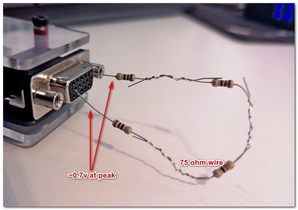
- Monitor/Display standards expect 0.7v input at peak color/signal into the connector (going into the cable), in a completed circuit. (Note: some specialty monitors can accept TTL).
- Monitor/Displays are terminated 75 Ohm internally.
- None of this is exact science - various monitors/cables have slightly difference resistances, +/-10% is probably okay.
The most important concept in all of this is that monitors are terminated 75 Ohm internally. You can verify this by taking 22ga. wire and shoving it into the DB15 (VGA) connector on the RGB and sync pins of your monitor, and measuring resistance between the leads and ground with your multimeter. The reason knowing this is important, is that any resistors you add in series on your device (between the IC generating the video, and the output connector which connects to your video cable), will form a voltage divider.
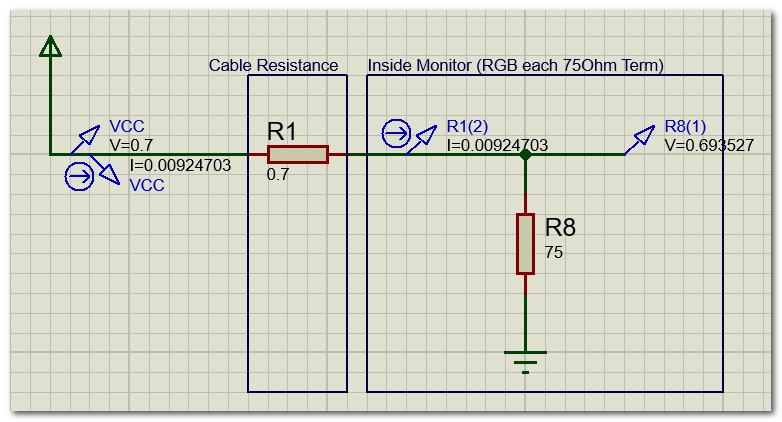
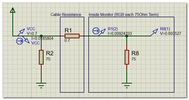
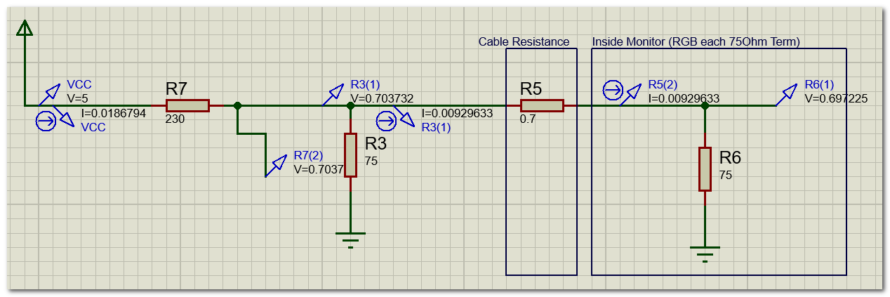
If your device video output lines (RGB/sync) are already outputting 0.7v maximum (or very close to), you don’t need any series resistors. If you were to add any in series, you’re going to form a voltage divider and your colors will be very dark. however to minimize transients on the line you can do your own 75 Ohm termination (parallel) on your device, it won’t affect voltage entering the cable. See the two images below for example. Note that my cable (in this case, VGA cable) has a resistance of 0.7 Ohm when I measured a pin from one end to the other, and my monitor was very close to 75 Ohm (@77). Really good VGA cables will probably be closer to 0.1 Ohms.
All the below diagrams were simulated using Proteus software.
Where the mathematics begins is if your video output lines (RGB/sync) output something greater than 0.7v by default. The most common of these being 1v, 3.3v, and 5v. I find it’s best you measure right off the video pins off the IC in an unloaded circuit so you’re getting the real voltage output to use in calculations. For example, in the Sweet15 I built is a 3.3v device but the actual voltage I see on the Atmel device pins is 2.98v.
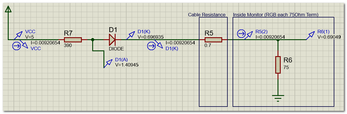
Below I give an example of a system where the video generator is outputting 5v, and must be tuned to deliver 0.7v. Again, the VGA cable resistance is about 0.7 ohms, and the monitor is internally terminated at 75 ohms. Depending on if you use a diode or not, or if you terminate your device at 75 ohms (and where), will affect resistor value. If I use a diode, I can get away with a lower resistor value as the diode will drop some voltage. If no diode, I need a higher resistor value.
In Figure 6, I terminate 75 ohms on the device to the right of the series resistor, which forms a voltage divider (negating the one the monitor would form), so the resistor value would be much lower in order to maintain ~0.7v.


The last thing I want to emphasize is that 0.7v is the standard in a completed circuit. Notice all the schematic simulations above are measured by the whole circuit. You don’t neccessarily need to see 0.7v on the connector edge of your device when it’s not connected to the monitor, as depending on your internal configuration, you may form a voltage divider when plugged into the monitor, which then gets you where you need to be.
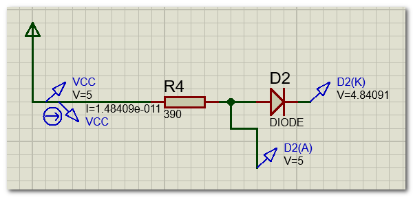
For example, the diagram below is our 5v example with the 390 resistor and a diode. If we measured it unconnected to the monitor, we will see ~4.84v…. which may be alarming. However, once it’s connected to the monitor, it will complete the voltage divider and we will observe close to the 0.7v standard (see Figure 3).
If you’re dealing with some sort of black box sealed device and unsure if internally there is a resistor in series, or really what behaviour to expect, you can wire 75 ohms between a video pin and ground on the connector (faking as if its connected to a monitor) and measure with a multimeter to know if the monitor will form a divider (in which case the voltage between the resistor leads is less than the voltage measured right at the female connectors). This will also tell you what voltage your monitor/display will receive and if it is within tolernace.