Using I²C with the Bus Pirate
May 12, 2019I²C uses only two bidirectional open collector or open drain lines, Serial Data Line (SDA) and Serial Clock Line (SCL), pulled up with resistors. Typical voltages used are +5 V or +3.3 V.
I won’t go into much detail on what I²C is, there is reams of information online about it; but here are some good articles if you need a background:
The ‘Bus Pirate’ is a universal bus interface that talks to most chips from a PC serial terminal, eliminating a ton of early prototyping effort when working with new or unknown chips. It supports many protocols such as SPI, JTAG, 1-Wire, and of course I²C!
You can purchase and read about the Bus Pirate here
The Bus Pirate connects to your computer via USB as it has an integrated “Serial to USB” convertor. As most computers do not have serial ports anymore, this is the best solution on modern systems. I personally use Tera Term as my serial interface. It can be downloaded here.
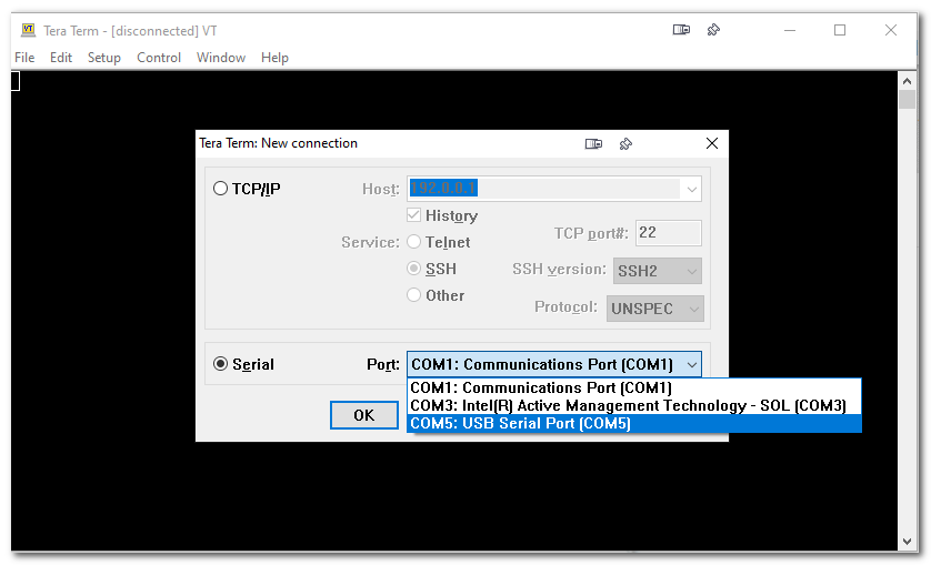
When you open a new connection you may see several options… it’s likely the Bus Pirate will show up as “USB Serial Port” as mine does here. Note that it will not show up by the name “Bus Pirate” (it’s not that smart of a protocal to fetch device names). If you’re dubious if you have the right device, merely unplug the Bus Pirate from your USB and see which line item dissapears and reappears when plugged in again.
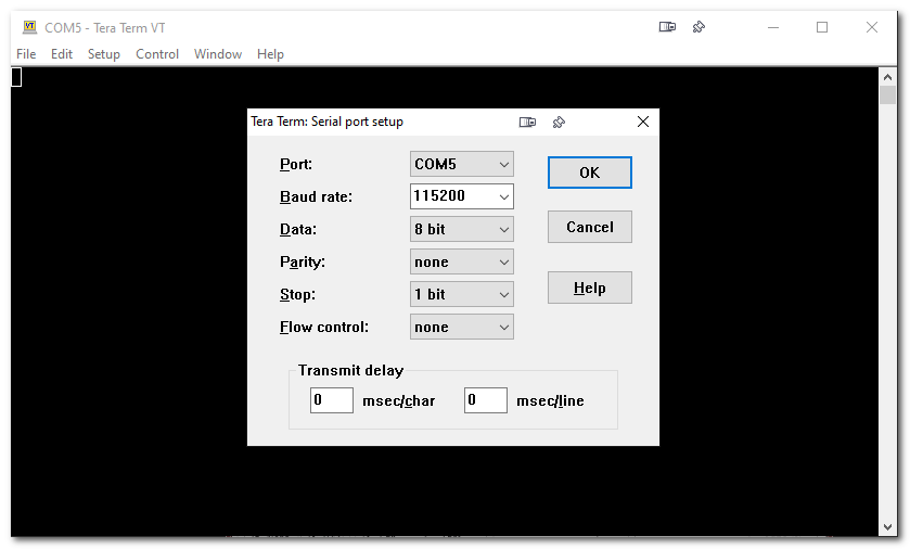
It’s important to set the device baud rate to 115,200 as I have done below. This is the speed at which the serial to USB data communicates with your terminal software (Tera Term). You will not get a response if it is set to anything else!
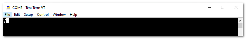
You should now be connected, you can tell with TeraTerm as it displays “COM5” in the header of the window (or whatever COM port your computer may have connected with).
To query the bus pirate for the main menu type ‘?’ and hit Enter.
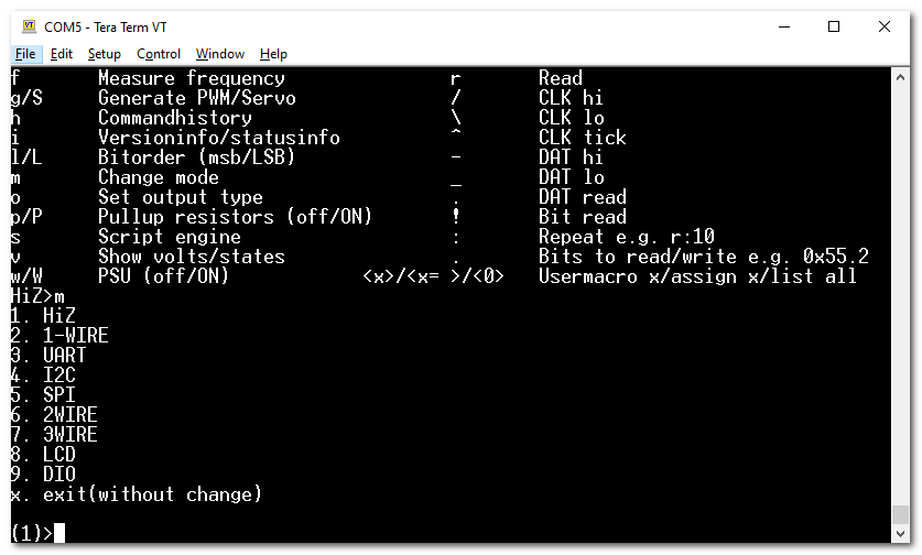
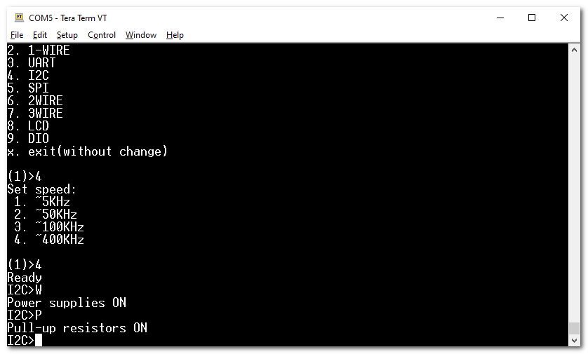
Below is the main menu… yours may differ slightly based on the firmware revision, but in general it is largely unchanged.
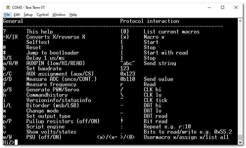
The first thing we will want to do is change the mode of the communication protocal between the Bus Pirate and our microchip/ASIC. This is identified as the command ’m’. Type ’m’ and hit Enter.
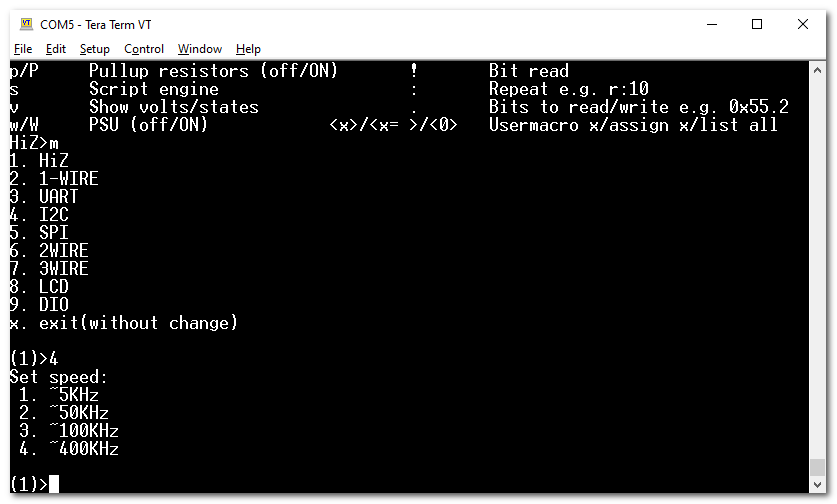
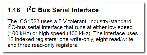
As I²C is option 4, type ‘4’ and hit Enter. Next you will be prompted with the speed at which your I²C device expects communication. These are all industry standard speeds. The ASIC I am using can handle both 100Khz or 400Khz. This is usually on the datasheet of the product you’re using. If you can’t find it you may have to take a few guesses - doesn’t take long with only 4 choices.
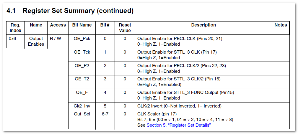
An exerpt from the datasheet of the ASIC I am using, which identifies both 100Khz and 400Khz communication as acceptable.
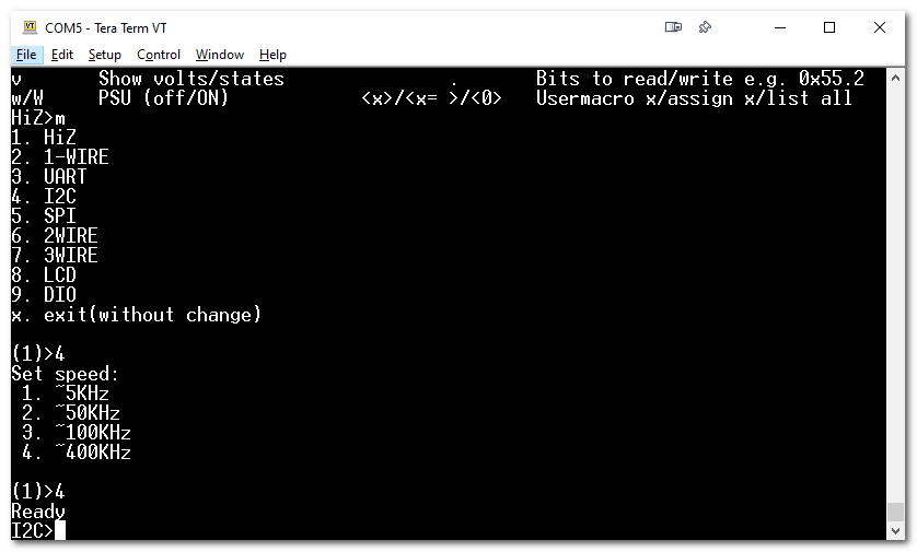
I’ll go with 400Khz, so type ‘4’ and hit Enter.
Next step is to power on the internal Power Supply of the Bus Pirate, which provides power output on the 5V and 3.3V pins. This is done for two reasons. 1) The 5V power pin will be used as a pullup voltage for the pullup resistor, and the 3.3V will be used to power my ASIC (which is 3.3v).
Right after that step, I will turn on the Pull Up Resistor. Note that they must be done in this order, or you’ll get a warning that there is a short or no voltage if you try to turn on the pull up resistor before the power supply.
You will be able to confirm the Power Supply is on as the VREG led light on the Bus Pirate will turn on.
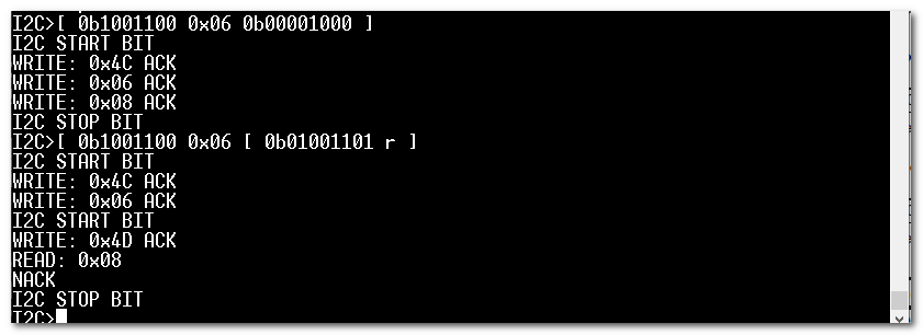
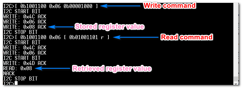
We are now setup to issue I2C commands to our ASIC. But it’s important to take a quick look at the data format our ASIC expects, in the manufacturer datasheet. As I2C is a standard, it’s practically gauranteed to be the same across every device, but it’s best to look through the datasheet and find a table such as the below as it will give you the device read and write addresses, which we will need for reading and writing to registers. There may be an off-chance the ‘Start’, ‘Ack’, ‘Nack’ sequence of events are non-standard (though really unlikely).
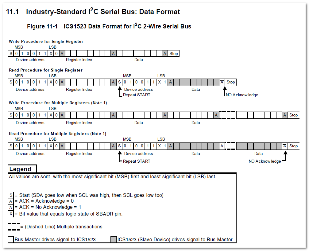
In the above you can see to write to a register, the protocol expects the following sequence of events:
- Start signal (Sent by Bus Pirate to ASIC)
- Device address (Sent by Bus Pirate to ASIC)
- Acknowledge (Sent by ASIC to Bus Pirate)
- Register address (Sent by Bus Pirate to ASIC)
- Acknowledge (Sent by ASIC to Bus Pirate)
- Data Byte of 8-bits width (Sent by Bus Pirate to ASIC)
- Acknowledge (Sent by ASIC to Bus Pirate)
- Stop signal (Sent by Bus Pirate to ASIC)
- Send re-occuring updates of key metrics from spreadsheets, via SMS at click of a button
- Implement “IF” conditional statements to show certain data if they breach a threshold or target value
- Easy to build out natural langauge sentences by concatenating cell values into a pre-determined script