Kickstarter - GBSC Slipgate and Quad Damage (2021) [Completed]
January 12, 2021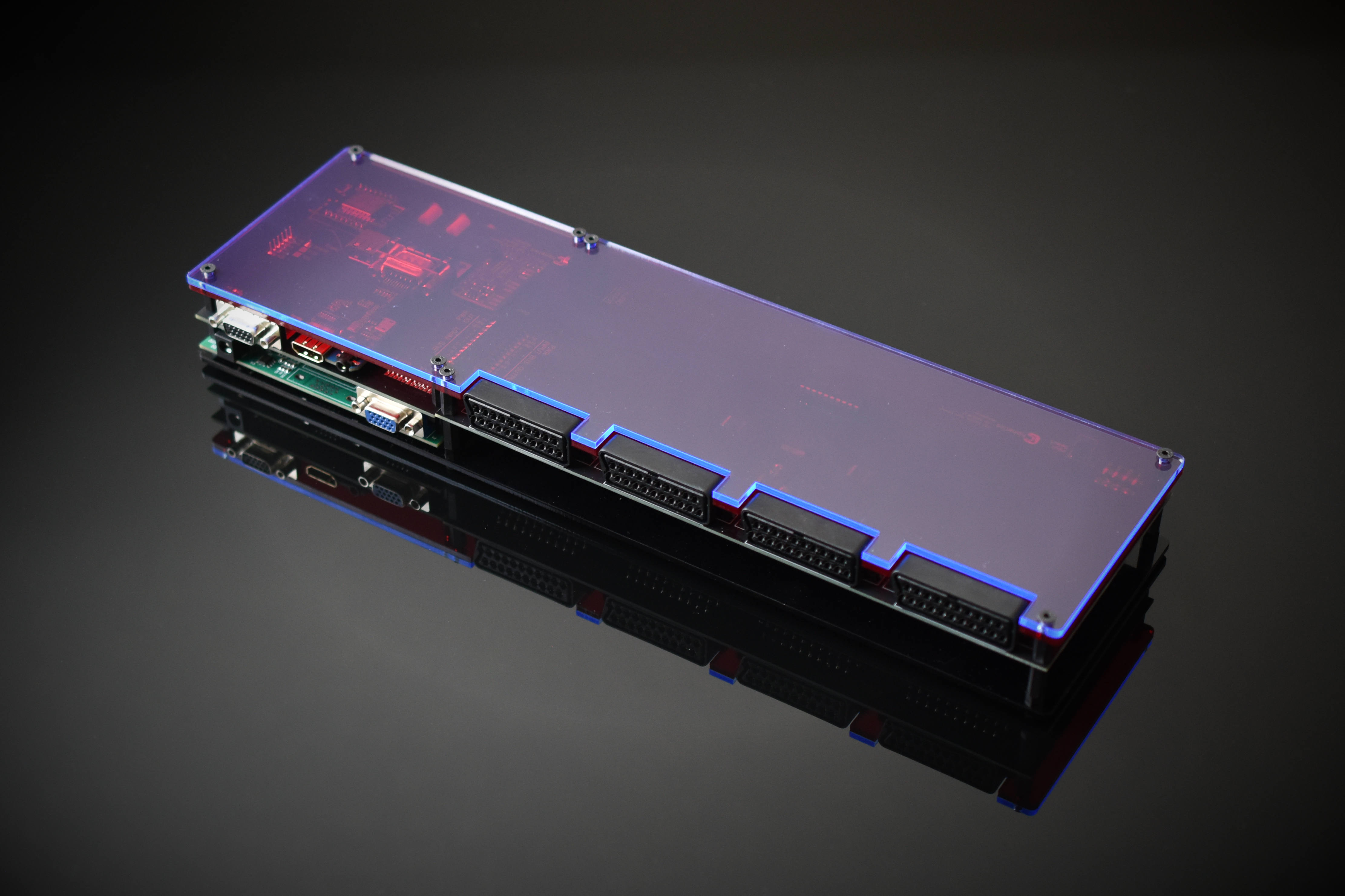
At the beginning of January 2021 I set out to do my first Kickstarter project, which aimed to extend the GBS-Control video upscaler hardware with refined design and multiple inputs. Much of the Kickstarter writeup is repeated here, but I also outline some lessons learned inline with the article.
It didn’t dawn on me until after the Kickstarter, that this is very likely the only 4-port DSUB/SCART upscaling switch ever made; both privately or commercially. 4-port DSUB rotary KVM switches were fairly popular in the 80’s and 90’s, but of course with no upscaling…. similarily, 4-port SCART switches are pretty much unheard of entirely - the only close comparison being the privately made ‘gscartsw’ product (which has no upscaling).
Table Of Contents
Kickstarter Descriptions + Lessons Learned
Premise
This is a Kickstarter for a highly improved base model “GBS8200 video scaling board” typically used in many retro gaming applications, which are mediocre quality in their original design, but with the proper modifications become one of the industry leading video scalers available, at a fraction of the cost!
This modified design is nearly lag free, perfect for retro-gaming, and gives the added option of 4-port input switching! With options for both SCART and DSUB inputs, users have superior graphics quality & control when compared to the traditional method of video scaling, such as those presented on modern consumer televisions via other cabling methods (such as composite, component, and S-video) which is typically slow, blurry, and inaccurate.
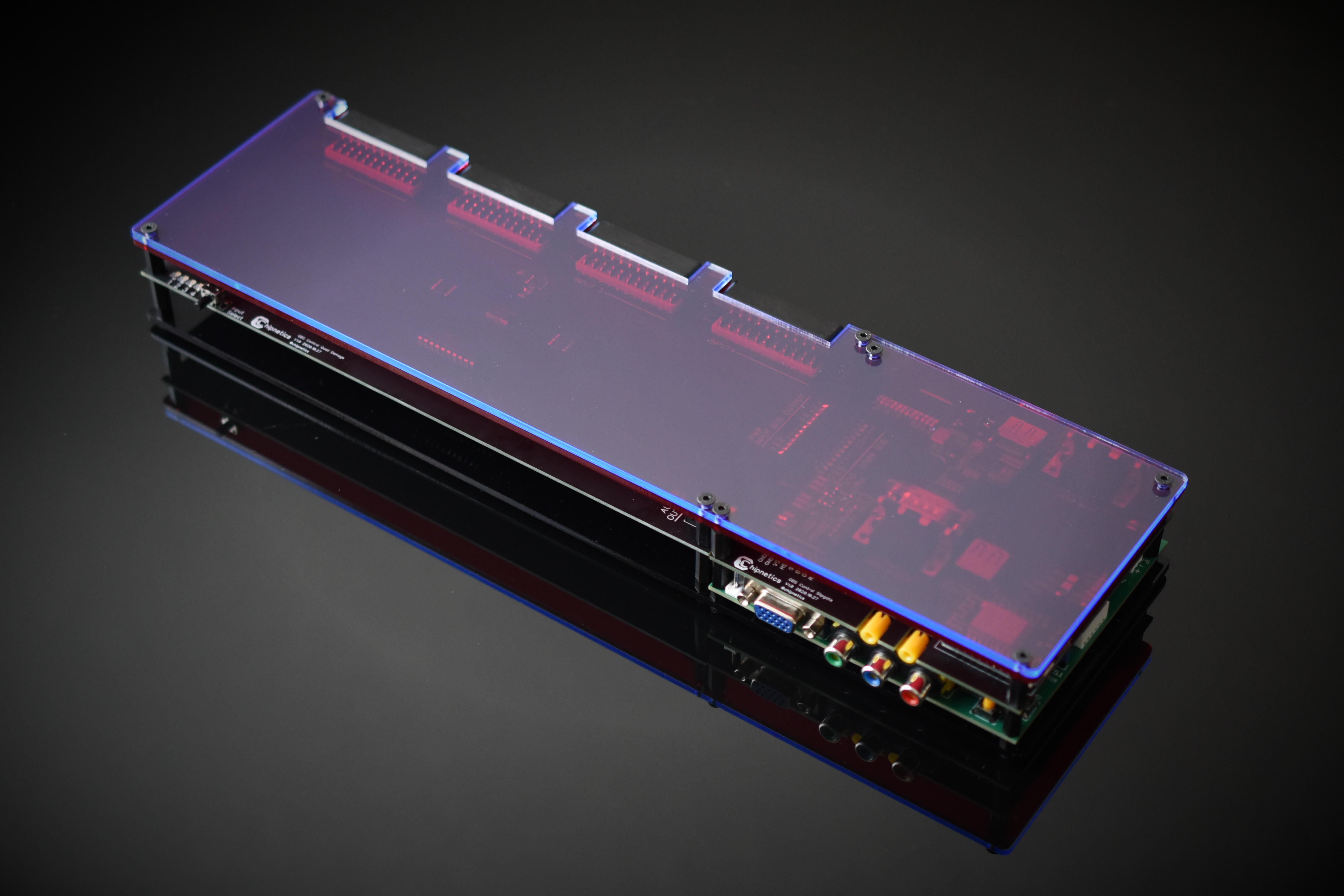
Two Hardware Components
- A shield (mezzanine board), to the GBS8200, called the “GBS Control Slipgate”
- A daughter board to the “GBS Control Slipgate”, called the “GBS Control Quad Damage”
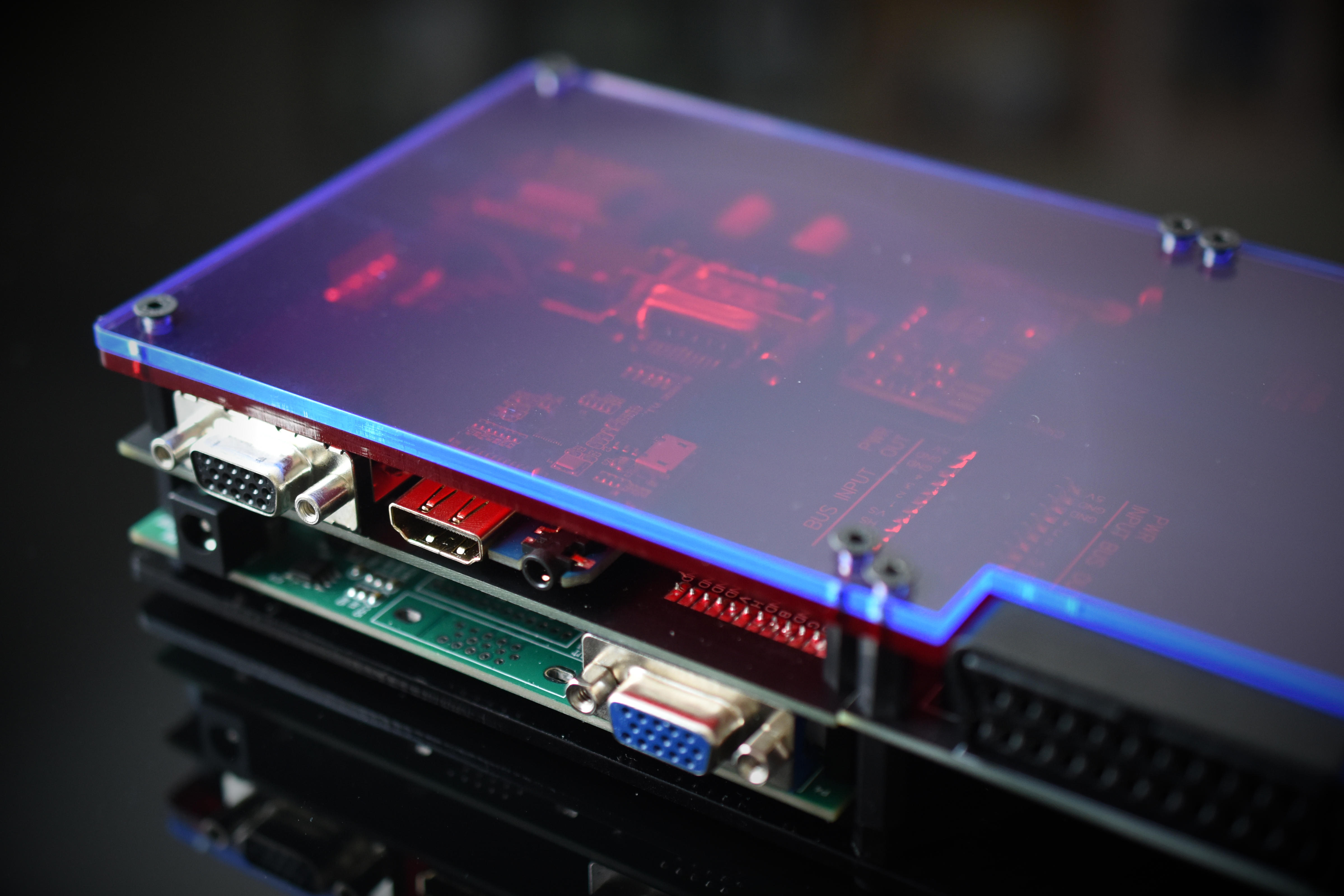
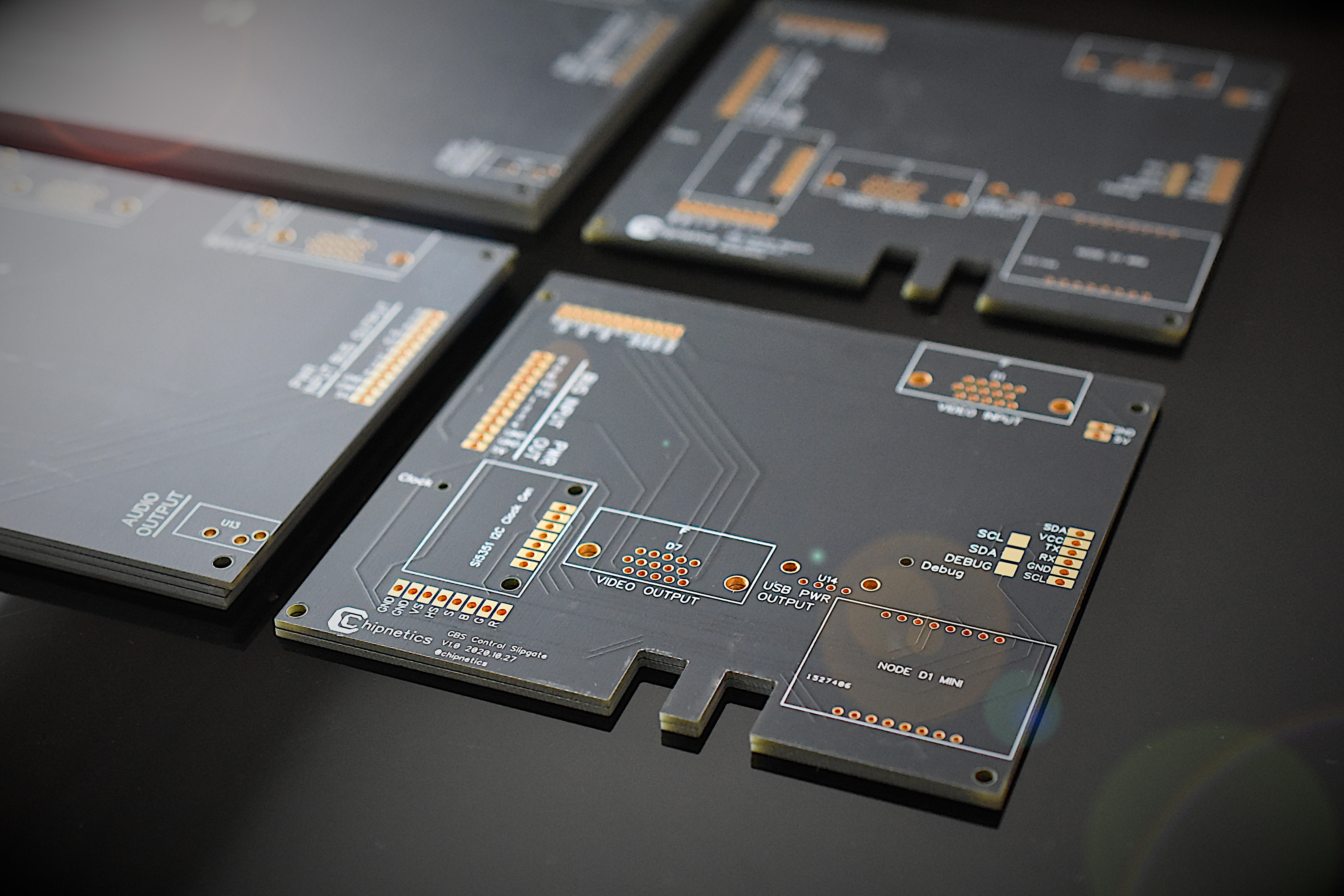
GBS Control Slipgate
The “GBS Control Slipgate” implements:
- An ESP8266 wireless module (Node D1 Mini), pre-programmed with the source code written by “Rama”, such that all video settings occur through a web-based interface.
- An external clock generator, to replace the base GBS8200 clock generator, for minimization of screen tearing at high resolutions
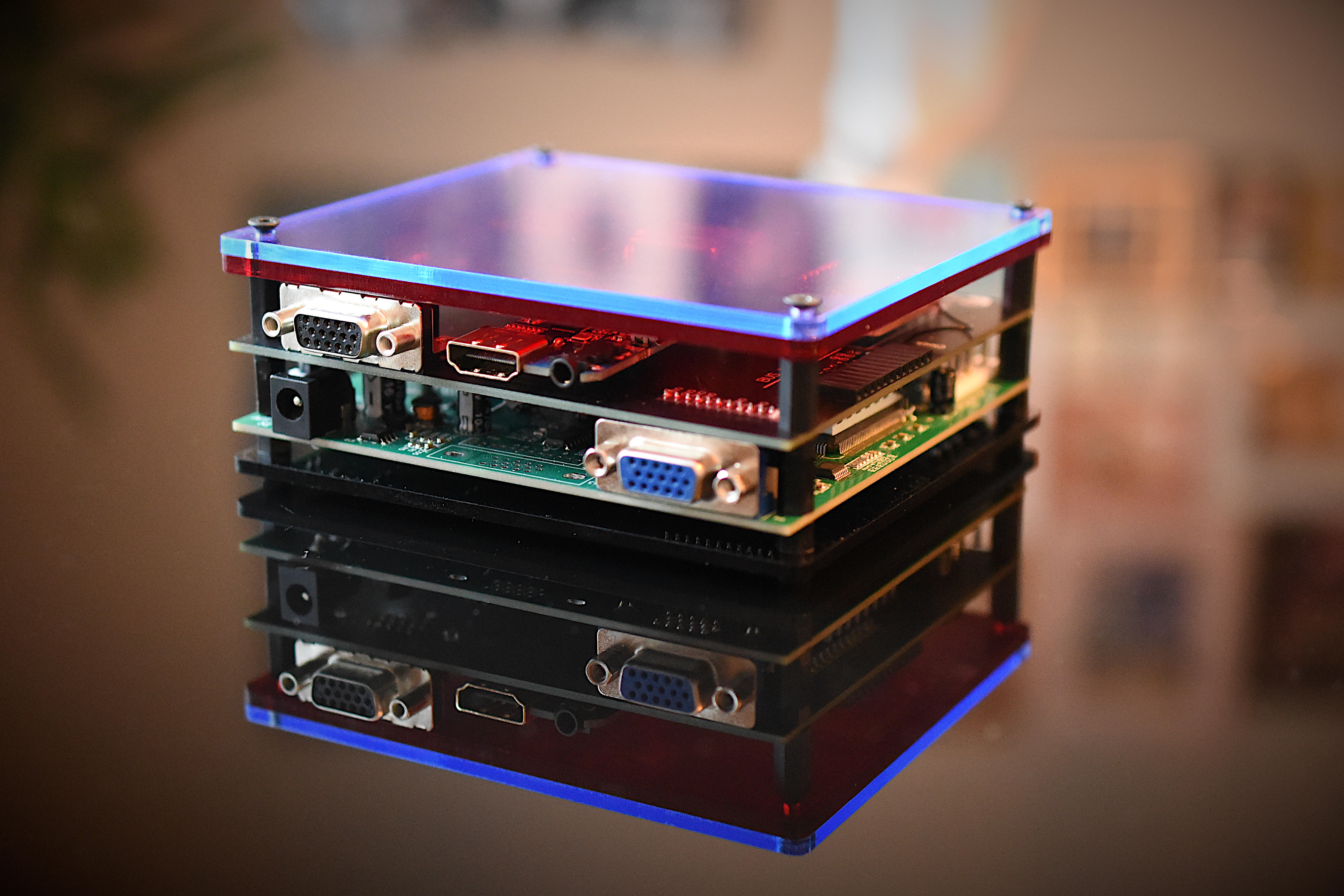
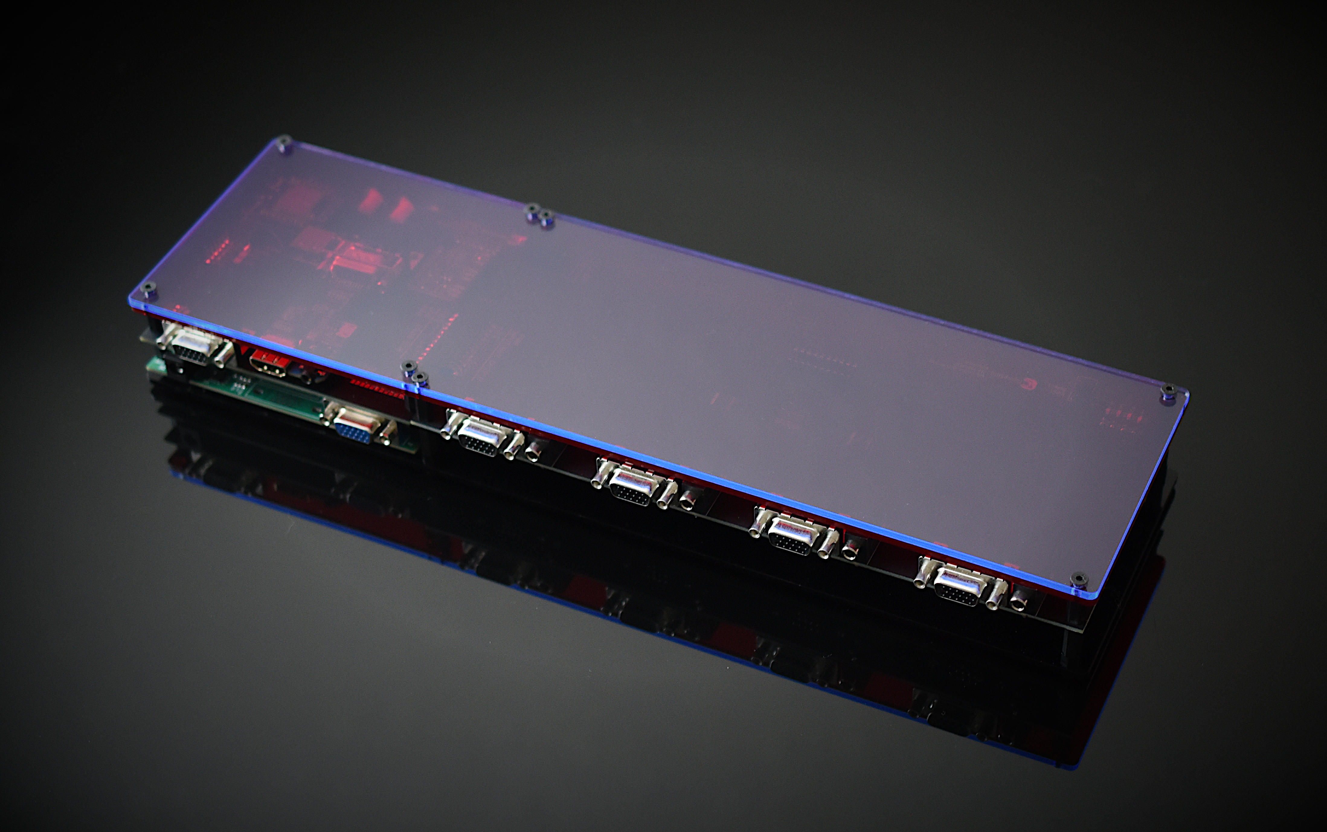
- A rear-facing DE-15 input (aka D-sub/VGA connector), to use in lieu of the front-facing connector, for better esthetics.
- A recessed DE-15 connector for flush mounting of a VGA to HDMI adapter; again, for improved esthetics as this would normally extend few inches from back of unit.
- An integrated Type A USB power connector for the VGA to HDMI adapter, for one less power adapter on your power bar!
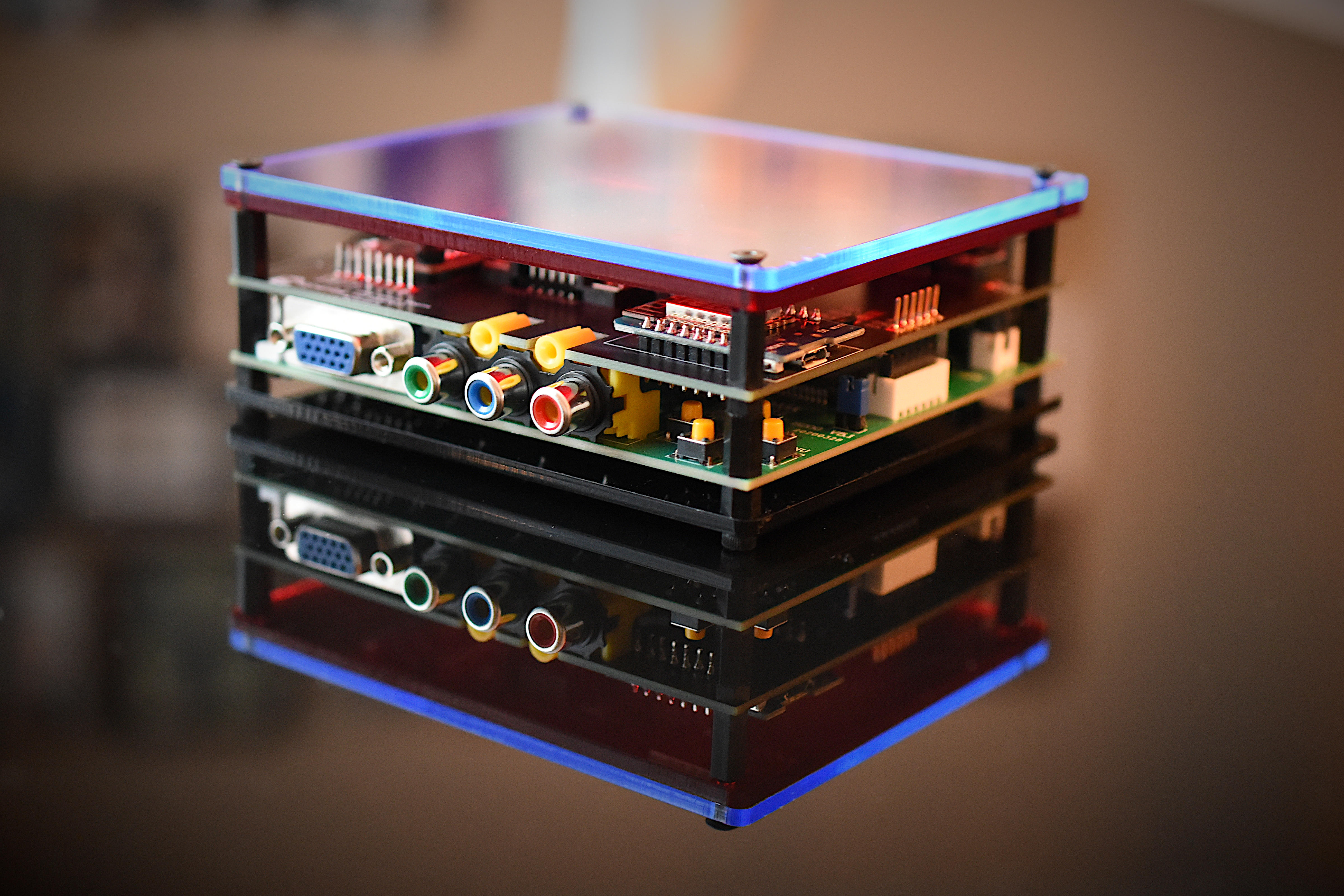
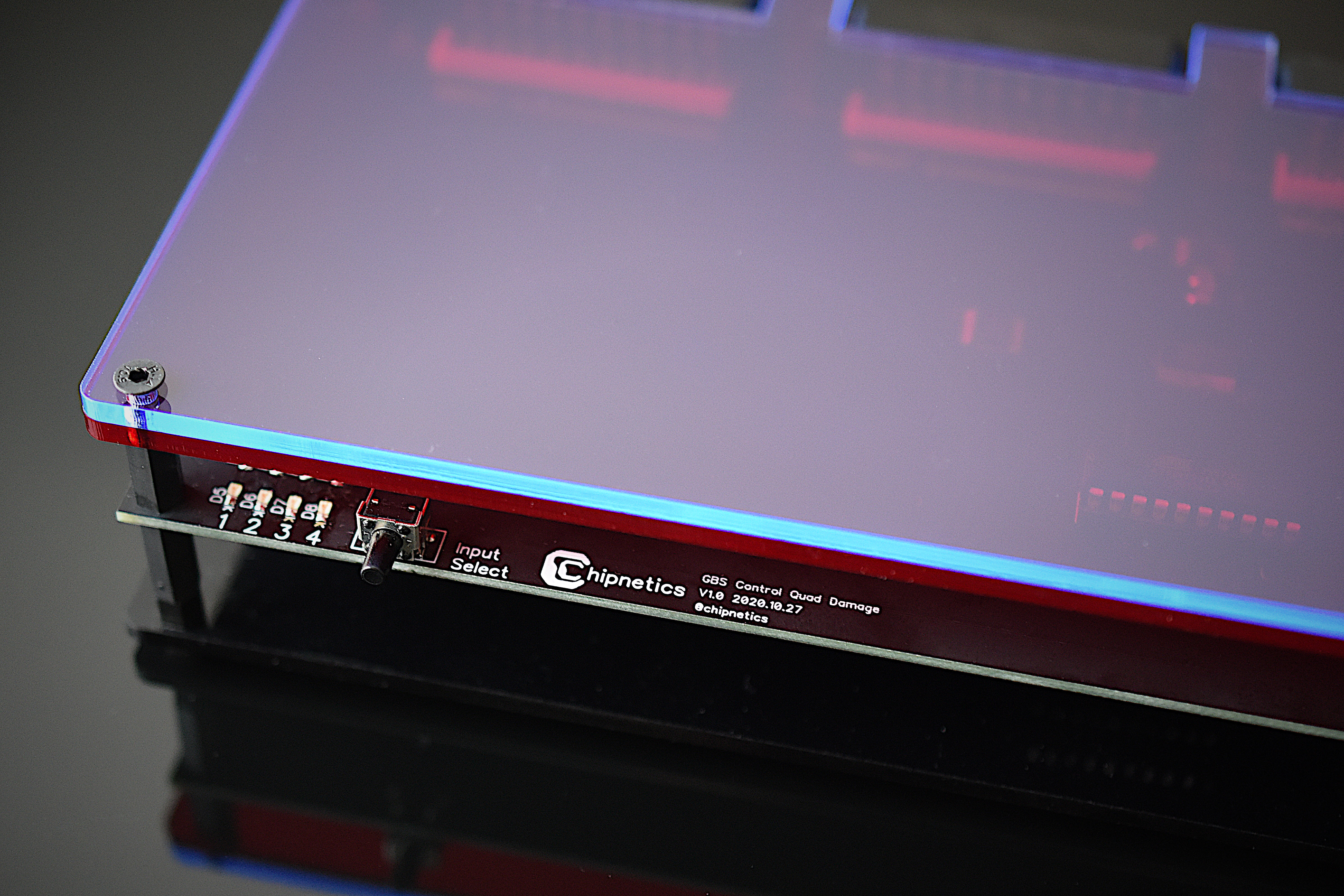
GBS Control Quad Damage
The “GBS Control Quad Damage” expansion board implements:
- 4-port autosensing with two choices for video & audio input (SCART and DSUB)
- Manual push-button control of switching between inputs.
The GBS Control Quad Damage detects new signal inputs and automatically switches to the latest video signal when present. However, you can manually change inputs via a push button; additionally, you can disable the auto-switching if so desired.
Pledgers have the choice of one of two input options (SCART or DSUB/DE-15), and can decide at the conclusion of the Kickstarter.
- Input Option 1: SCART (Euroscart) including an integrated sync signal stripper.
- Input option 2: DSUB DE-15 (VGA connector) and 3.5mm audio.

Many legacy devices and gaming consoles have readily available options for DSUB and SCART cables; with zero or minimal internal modifications required to directly plug-and-play.
Zero Internal Modifications (Plug-and-Play SCART and/or DSUB cable solutions exist):
- NTSC/PAL PlayStation 1, 2 and 3
- NTSC/PAL Original XBOX
- NTSC/PAL Sega Dreamcast
- NTSC/PAL Sega Saturn
- NTSC/PAL Sega Mega Drive / Genesis
- NTSC/PAL Super Nintendo (non SNES Jr Version)
- PAL Nintendo Wii
- PAL Nintendo GameCube
- NTSC/PAL TG-16 / PC Engine
- NTSC/PAL SNK NEO GEO AES
- ATARI ST, 65XE, 800XL, JAGUAR
- Commodore C16, C64, C64C, C128, VIC 20
- X86 Computers & DSUB graphics adaptors
Minimal Internal Modifications for SCART/DSUB cable support:
- NTSC/PAL Nintendo 64
- NTSC/PAL Super Nintendo (SNES Jr Version)
Complex Modifications (No easy Plug-and-Play SCART/DSUB cables, but console modifications exist for support thereof):
- NTSC Nintendo Wii
- NTSC Nintendo GameCube
- NTSC/PAL Original NES
- NTSC/PAL PANASONIC 3DO
- NTSC/PAL TURBO DUO
Note that even if a SCART or DSUB Plug-and-Play solution is difficult to achieve or procure, the “GBS Slipgate” has a component video input for equally as impressive visual results!
Hardware Specifications
- Ability to balance the amplitude of the three primary color signals - R, G, B
- Supports CGA/EGA/VGA/YUV Component Signal Input
- Supports VGA Output (640 x 480, 800 x 600, 1024 x 768, 1360 x 768)
- CGA/EGA/VGA signal auto scan (15KHz, 24KHz, 31KHz)
- YUV Component signal auto scan (480i, 576i, 720i, 1080i, 480p, 576p, 720p, 1080p)
- Supports image position control and image zoom control
- True digital 24-bit A/D converter for true 16.7-million color conversion.
- Supports many VGA monitors (CRT, LCD, PDP, Projector, etc.)
All hardware-based pledges include the options listed in the pledge, and also the modifications of:
- 100ohm 1% resistor mod between sync and ground
- 22uF Nichicon electrolytic cap on C11 of the GBS8200
- Removal of potentiometers, and bridging of RGB lines (values controlled via firmware)
Also included is a high quality, highly reviewed, Triad Magnetics 5V power supply. These power supplies are Type A NEMA (used in Americas, Thailand, China and Japan); thus, power outlets from other regions will require a travel adapter or different PSU (not included).
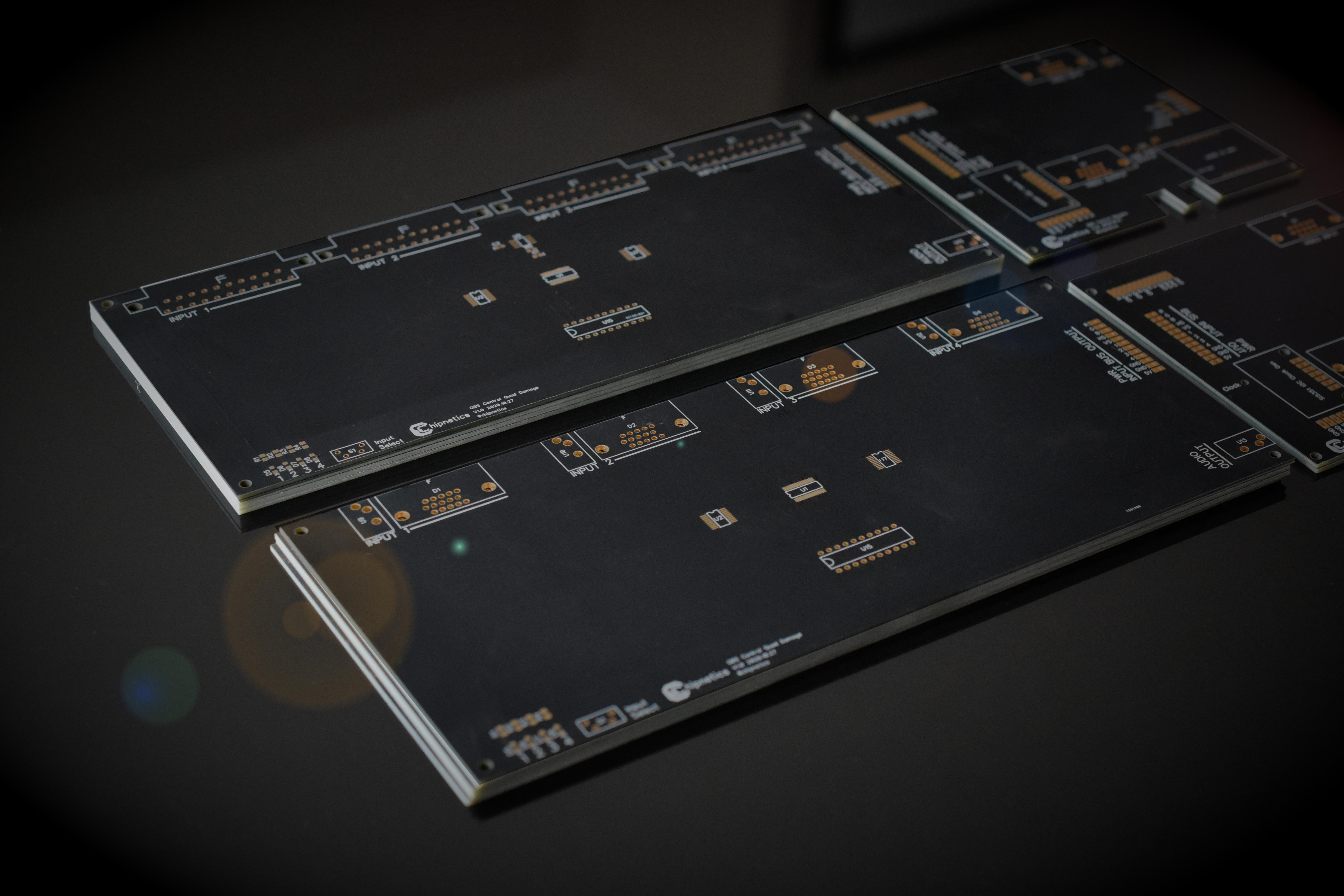
Two acrylic case designs are used; a smaller one for Slipgate-only pledges, and a larger, monolithic case, that is for Slipgate + Quad Damage pledges (as seen in the photos above).
Both GBS Control Quad Damage and Slipgate boards are of high quality, finished in matte black solder-mask and beautiful ENIG (Electroless Nickel Immersion Gold). Quad Damage boards will be assembled by a pick and place PCB fabricator, while Slipgate boards will be hand assembled in our facility.
An instruction manual is also included with all hardware pledges!
Electroless Nickel Immersion Gold finish on matte black silkscreen
Firmware Support
The GBS Control Slipgate utilizes the ‘Rama’ GBS-Control GitHub project (found on GitHub) as modified firmware for the original hardware. Credit and attribution specifically go to programmer Robert Neumann who spent significant energy making this firmware a reality. His hard work has been released as GNU GPLv3.
This Arduino-based project is pre-programmed onto the ESP8266 wireless module (Node D1 Mini) on the GBS Slipgate and acts as the new brain for controlling the pixel perfect video scaling operations. It also gives the added luxury of web-based interface control such that users don’t need to get off the couch and can use their phone/laptop/desktop to modify output video & scaling parameters such as resolution, screen position, brightness, scanlines, and advanced settings.
Chipnetics is extending the Rama GBS-Control GitHub project one step further! The GBS Control Quad Damage has been designed to output to the GBS Control Slipgate an indicator of which port is currently active. A fork of the GitHub project will be done such that a corresponding saved profile will be loaded for each input, giving the ultimate flexibility in input-specific configurations. For example, you may have different preferences for a Super Nintendo versus a Neo Geo; and want them instantly loaded when either console becomes active!
Post-Kickstarter Topics
Rama GBSC Source Code Modifications
The following defines were added, which corresponded to the traces coming off the ATTINY-2313, which indicates which console is active.
|
|
In the setup() function the following was added. Usual stuff; setting the pinmode to input, low logic, and attaching the interrupt handlers.
|
|
The below was commented out…. unfortunately. Anywhere Rama set the LEDON, notably to indicate sync, was commented out. See the Kickstarter Lesson Learned above.
|
|
The following functions were added as interrupt handlers. Note that the D1 Mini requires the function to have IRAM_ATTR pre-fixed, otherwise the D1 Mini does a hardware reset whenever an interrupt is called (yeah, wut?). This actually took the most amount of time to figure out, as anyone who has done embedded programming could likely fathom… You could probably get away with one interrupt handler and have a bunch of if-statement logic; but best to get out of the ISR fast as possible.
|
|
In function “handleType2Command” saveUserPrefs() was moved to in the case statement to take place first. Otherwise the mode switching resulted in the wrong preset slot being loaded (off-by-one). This function handles WebUI clicks by checking if a value for ’typeTwoCommand’ has been set. In the interrupt handlers we had set this to ‘3’; which is handled by the case statement below, for selecting preset slots.
|
|
Proteus IC Switch Logic
The switching logic, programmed on the ATTINY-2313, was designed in Proteus 8 Professional. Proteus is an excellent all in one tool for layout of a schematic, and simulating the performance of firmware code.
The source code, shown below was compiled in BASCOM-AVR, and is written in BASIC.
|
|
The example layout in Proteus, for simulation of the control logic:
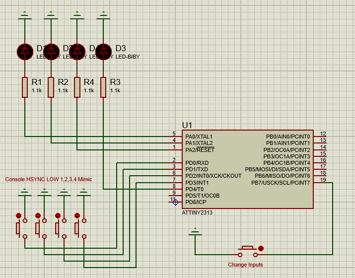
Image Quality Improvements
The HDMI adapter, in hindsight, probably is more detrement than benefit. It is enough load on the whole unit as to take the brightness of the image down measurably. In cases where users do not require HDMI, it is suggested to remove it entirely (including disconnecting the USB cable). You can still use the recessed DSUB header for a VGA cable if you want simultaneous outputs; however the cable will have to be wedged in at a slight angle - although low profile VGA cable housings do exist - they are hard to find.
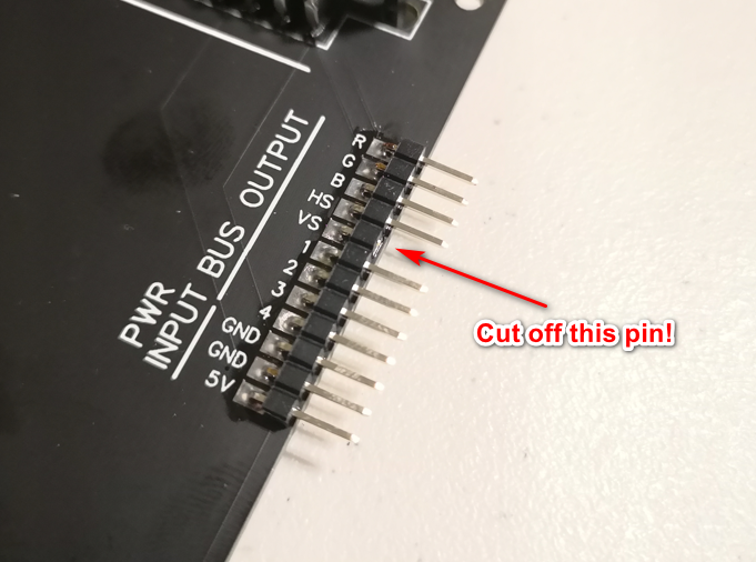
SCART difficulties with NTSC/PAL signal detection
Only applies to a few SCART Quad Damage units…
Unfortunately, some initial units shipped with this issue before it was detected. Quad Damage units to which this DOES NOT apply, have a sticker under the bottom acrylic labelled “FW1”.
It appears some of the sync seperators on some units spew out unusual Vsync signals - unsure if this is a batch issue from Texas Instruments, or an issue in PCB fabrication.
The corrupt Vsync signal ends up in the firmware not recognizing the signal as NTSC/PAL and instead classifies the signal as “VGA” or “Unknown”, which result in different scaling algorithms being applied. Luckily, the Vsync signal isn’t even required as the GBSC will gracefully handle Csync over Hsync by itself.
The fix is relatively simple and will take ~20 minutes, but involves some manual work:
-
Take off the top acrylic.
-
Remove the nylon stand-off’s from the Quad Damage board.
-
Slide the Quad Damage board off from the Slipgate board.
-
Cut (or bend) the pin off that is labelled “VS” as in the image below.
-
The firmware also has to be re-applied. Instructions are given below.
-
Download the ESP8266 Flasher utility Here
-
Download the pre-compiled firmware (.bin) file Here
-
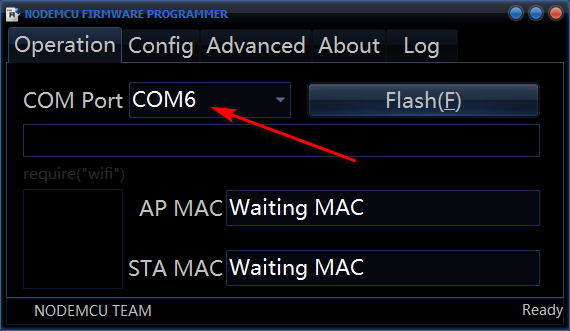
With the Quad Damage board still disconnected from the Slipgate, connect the Slipgate to your computer with a USB cable.
-
In ESP8266Flasher.exe, select the relevant COM port for your setup. You may have to disconnnect/connect the USB to see what port to select.
-
-
Navigate to where you saved the .bin file by clicking the gear icon.
-
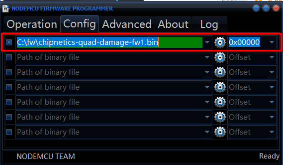
-
Match the settings abvoe on the “Advanced” tab.
-
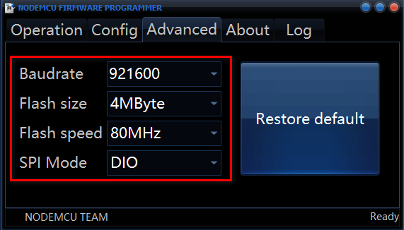
-
Go back to the “Operation” tab and click Flash.
-
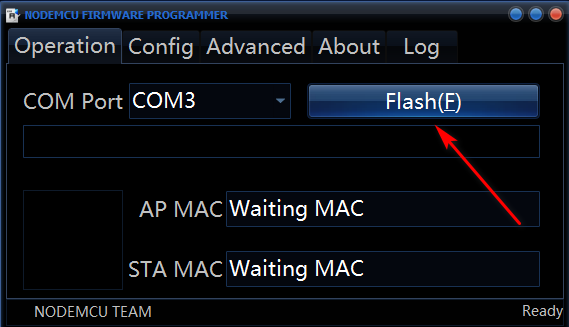
-
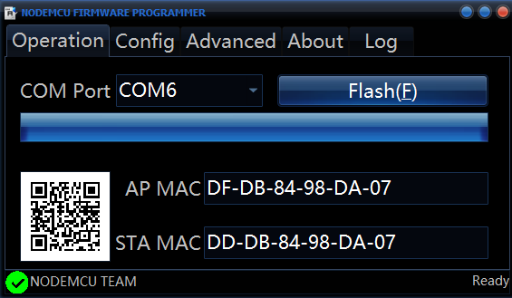
After a minute or so, the device will be flashed. The progress bar will fill accordingly. You can also see the blue LED on the device flicker as data is transferred. Disconnect from USB and re-assemble the unit as before.
-
Closing Remarks
The Kickstarter was rewarding in the sense I can say I did it. It’s questionable if I made any profit at all, although that wasn’t really my intention from the start. I don’t intend to go calculate what I made or lost.
During the campaign I read some comments the pricing was astronomical, which is interesting, as I probably worked for under $2/hr when I consider everything from the hours of research, design, marketting, procurement, communication, assembly, and distribution. Of course, these comments will always surface no matter who or what is involved - privately or commercially.
Items I mis-considered were:
- Price of acrylic (especially given the size, double layer, and special order colors).
- Packaging time wrapping everything carefully, folding boxes, printing labels, taping, etc.
- Cost of multiple doorstep pickups to mitigate risk. Specifically, there was too much risk sending too many units at once.
- PCB fabrication “trial and error”. A mistake instantly costs a lot of money (both from the fabricator, and DHL) and waiting time for a future attempt.
- The integrated circuit shortage made everything much more expensive.
- COVID no doubt had some sorts of psychological effects on everything.
I had a cute fantasy of taking a picture of all the units assembled, in one epic photo, never to be reproduced. However, given I was already behind schedule I thought it best to not bother and just get shipping!
It’s 70% likely I will sell these in the future with a redesign in 2022. The most notable difference will be the switch selection will be purely analog with a five-pole single-throw switch of sorts. The push button integrated circuit and logic gate approach is marginal overkill; but I don’t think anyone will mind a slide switch. I will definitely be removing the HDMI adapter as well, and intend to do so in my existing product line too.
Thanks for reading, please reach out if you have any questions or an ambitious project of your own that may extend this work. I am happy to help!